Overview
Rather than using off-the-shelf PDB modules, this board was designed from scratch to meet the specific voltage and current requirements of the drone’s subsystems. The result is a tightly integrated power solution with three independently regulated rails.
| Date | April 2026 |
| My role | Hardware Design |
| PCB | 2-Layer, KiCad |
| Input | LiPo/Li-ion via XT90 connector |
| GitHub | hardware-portfolio/DronePDB |
Features
- 3 Independent Buck Converters — Each designed to supply a specific voltage rail for the drone’s subsystems
- LiPo/Li-ion Input — Accepts direct battery input via XT90 connector
- Designed for the size and weight constraints typical of drone platforms
Voltage Rails
| Rail | Purpose |
|---|---|
| Rail 1 | Flight controller / compute |
| Rail 2 | Peripheral subsystems |
| Rail 3 | Sensors / low-power logic |
Hardware Highlights
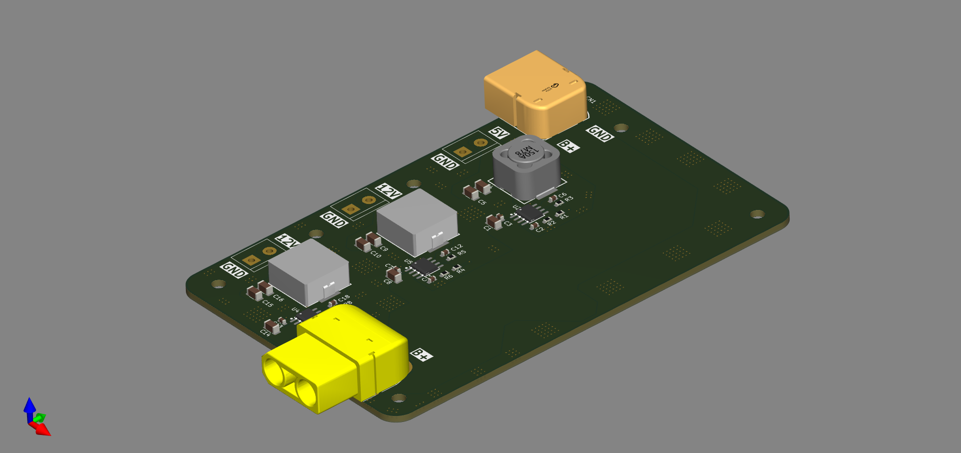
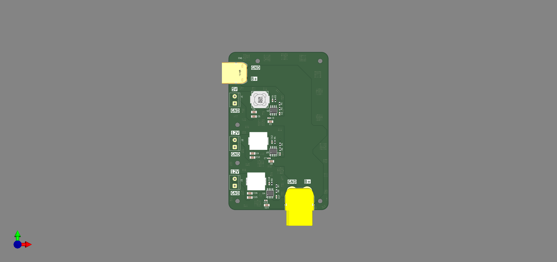
All three buck converter circuits designed from scratch — inductor sizing, feedback network, compensation network, and PCB layout — rather than using pre-built modules. Full control over efficiency, switching frequency, and output ripple.
High-current PCB layout — Power planes sized for the current demands of each subsystem. Careful attention to switching node copper area and decoupling placement to minimise EMI. Input and output capacitors placed tight to each converter cell.
Size and weight constraints — Drone platforms demand compact layouts. Component placement prioritised density without compromising thermal performance or layout integrity.
Images